IV Configuration and Benefits
ConcordLift ™ has no fuselage, instead there is a main cargo flying wing and auxiliary wings connected by the vertical fins. The description and dimensions given are for illustration only. They sketch a shipping container aircraft. The actual shapes and positions of the parts will be determined in design engineering and the final appearance is likely to be somewhat different.
This novel configuration creates a new type of aircraft capable of very heavy payload for new uses. This should not be seen as a larger type of air freight, rather a flying version of sea borne shipping. It is not expected to be a competitor for existing airfreight. It will transform the economies of interior regions by ending their isolation from ocean freight.
Before this configuration, very large, deep chord, wings could not be stable in ground effect - landing and taking off. Self reinforcing instabilities were unmanageable. The deep cord wing, moving slowly, creates a venturi between wing and ground. When the trailing edge is closer to the ground than the leading edge, air pressure is lower at the trailing edge, pulling it even closer to the ground. The use of flaps makes the effect worse. The same effect occurs when one wingtip is closer to the ground. The ConcordLift™ configuration manages every variety of instability. For stability the shortest dimension between wing and ground must be located at the center of lift. This uses an inverted airfoil. The goal is to obtain maximum lift and at the same time the least negative pressure between wing and ground.
The angle of attack is restricted. If the bottom of the wing is flat, there is no angle of attack and insufficient lift. As the airfoil morphs to full inverted form, keeping the shortest dimension to the ground under the center of lift still limits the angle of attack. The inverted airfoil has a maximum angle of attack, with a thickness 10% of the cord, about 5.7° on the ground. It is not the best AOA but close to good enough. Normal angle of attack for best rate of climb is 6-8°. Angle of attack for normal flight is about 3°.
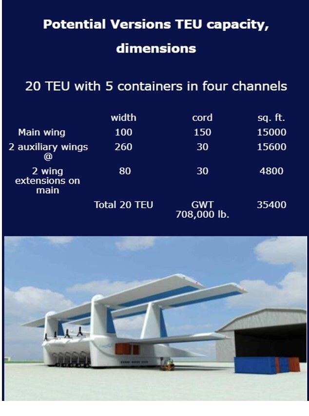
The Main Wing, Slots and SpoilersThe very large, thick, flying wing cannot have flaps but can have leading edge slots and spoilers. The airfoil remains the same from 100 ft. cord and longer. At 200 ft. cord, it would seem to be thicker than necessary, but a thinner wing would greatly reduce the angle of attack on the runway. Wingspan is up to 260 feet, thickness to over 15 feet, and chord to over 150 feet. This is about the same as the total dimensions, the 80 meter box, for large aircraft. A 150 ft. cord, 260 ft. span would be able to carry 20 53’ trailer bodies or 52 20’ shipping containers in four rows of cargo channels from wing tip to wing tip. The center of the load, mid point of the channels, has to be at the center of the lift, which is about at 1 / 4th of the cord. Container channels cannot fill the wing. Each end of the container channel has a door, so there are 8 doors and fast loading time.
The Main Wing boundary layer air controlThe great wing surface and flight conditions create high drag from the boundary layer air. Until the numbers and experiments are run, the actual extent of the issue is unknown. Accurate numbers would make possible cost / benefit analysis of solutions. The great internal volume makes possible various ways to manage. A historic suggestion was to perforate the wing surface and draw the boundary layer inside. That may be practical on this aircraft. The great wing interior would be a plenum. The exhaust fans could be fanjets that also provide thrust. The fanjets would not “know” that their intake was restricted. All they would sense was the reduced intake air pressure. Since fanjets have low intake pressure at high altitude, that would be no problem.
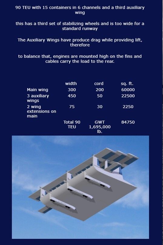
Auxiliary Wings, adjustable incidence, high lift devicesThe auxiliary wings are major structures. They are mounted on pivots so the angle of attack can be changed. The auxiliary wings must be positioned so they do not interfere with each other or the main wing. The optimum position will take some study but if they are positioned too high there is minimal penalty. Since the auxiliary wings are fixed to the fins at both ends, they must have a suspension to absorb the turbulence cantilevered wings absorb by flexing. They provide the extra lift needed at take off and landing. Flaps and slots can extend their full width, since this concept can use a portion of the wing as flaperons. The adjustable incidence is necessary to flare for landing and rotate for take off. At optimum angle of attack and with high lift devices, a wing can produce 2 ½ times as much lift as considered normal. If the auxiliary wings and extensions are 20% of the total wing square foot, 2/10 in area, at optimum angle of attack, they provide 5/13 in lift.
Wing Extensions, adjustable incidence high lift devicesThe main cargo wing might only extend 5 TEU wide, 100 ft or less. If the deep cord cargo wing is 100 ft wide there would be room within the 80 meter wide airport limitation for 80 foot wings extending out the sides for a total 260 ft wingspan. Those wings would be similar to standard aircraft wings. If the center cargo section was 260 foot wide, the extensions would not fit the limitation, however extensions could be made to fold like those for use on an aircraft carrier. The total flying width could then be 460 feet with 100 foot extensions while the width on the ground remained 260 foot. Wing extensions could be positioned at the ends of the auxiliary wings as well. That would give a combined wing span of 460 foot with only 260 feet of the total consisting of the deep cord cargo section. The aircraft would be in ground effect well over 200 ft above the surface. The Wing extensions could have the angle of attack fixed or pivoted. They could have flaps and slots their entire span.
The total lift of the ConcordLift ™ is not determined by the deep cord cargo wing portion alone. Wings work together in harmony - “Concord” to accomplish what otherwise cannot be done.
Yaw, directional change and roll - active flight stability
Aircraft used to be designed for passive stability. The surfaces at the rear provided the drag necessary for directional control. Proper design of the front and rear auxiliary wings can achieve that for this aircraft. The amount or degree of passive stability has been decreased by modern computer active flight stability which is expected to be part of this aircraft as well.
At the front and rear of the main wing are vertical fins with rudders. Their primary function is to carry the tension - lift from the auxiliary wings to the main wing. They need no more area than needed for directional stability Tension is the lightest and least space demanding load to transmit. The fins might be much narrower than illustrated. Since flight is slow, cable braces might also be used. At altitude, the ConcordLift ™ will turn and bank in the normal manner. In ground effect, the control for direction and yaw is by variation of engine power. Power is increased on the outer engine, The outside wing moves faster than the inside, therefore has greater lift causing the plane to roll. Spoilers automatically compensate for the increased lift, so turns can be with the wings level. In addition to the spoilers, the lift from the auxiliary wings, wing extensions, can be varied, to be used as ailerons to manage roll.
Pitch, climbing and descending
Pitch control for the main wing is provided by auxiliary wings. They can be used independently or together and control the angle of attack for the main wing. The auxiliary wings, higher than the main wing, are affected less by ground effect instabilities and provide good flight stability.
Engines
The slow speed, cruising power of the largest ConcordLift ™ is less than a 747 needs for high speed flight. Engine weight is not an issue with ConcordLift ™. Many variations of power are possible. Instead of fanjets to exhaust the main wing plenum, propellors could be mounted above to wash over the top of the wing, increasing lift. Many, small engines might be an advantage. Heavy engines in front of the center of lift could help balance the structure behind. Flights may last several days, over 9000 miles. Heavy, fuel efficient engines, could make for less total weight.
Landing gear and operation for landing and take off
The landing gear is very unusual. There are two separate types of gear. In addition to the normal main gear, there is a second set of “stabilizing gear”. The closer the main wing is to the ground the greater is the danger of instability. The following thirty foot dimension for the stabilizing gear is a “guess” at what might be sufficient. The ten foot dimension for the main gear is good for loading. A truck can unload at one wing tip, drive underneath and load on the other side. The “guess” is 10 ft. is too short for safe landing.
First contact with the ground is made with the main wing 30 feet above the runway by very large 10 ft. diameter wheels. This stabilizing gear can roll over most obstacles without digging in. Those wheels carry a portion of the total load while the rest is carried by the lift from the wings.
On landing: The auxiliary wings flare, change the angle of attack, for maximum lift. The suspension of the stabilizing gear is controlled to remain at maximum stiffness until all the wheels of the stabilizing gear have ground contact. After the aircraft is on all the stabilizing gear, at flying speed, 30 feet above the runway, brakes deploy. As the craft losses lift, the stabilizing gear is controlled to retract evenly until the weight settles on the main landing gear closer to the ground.
At take off: The auxiliary wings rotate for maximum lift. The ConcordLift™ lifts off from the main gear while the stabilizing gear, still in contact with the runway, carries a portion of the load. The gear legs are controlled to extend uniformly, maintaining stability. The extension of the stabilizing gear legs may be powered, lifting the aircraft without using lift generated by the engines, enhancing speed increase. The aircraft leaves ground with the main wing already 30 feet above the runway.
ConcordLift™ has two separate take off speeds. The slower speed is when it has enough lift to unload the weight on the main gear. Then it is able to raise the aircraft while the rest of the weight is still carried on the stabilizing gear. As the distance between the ground and main wing increases, the force of the venturi in between is reduced. The second take off speed is when the aircraft has developed enough lift to carry the total weight.
The main gear is of standard design. Standard runways are 150 feet wide. The 260 foot wingspan, 52 TEU, design has 16 stabilizing wheels in 4 x 4 wheel sets extending 120 feet and 10 x 4 for 40 main gear wheels, a total of 56 wheels. The heavy load is distributed over the total runway surface. Additional main gear could extend the full width of the aircraft for unimproved landing fields. The multitude of landing gear creates drag, increases the air pressure under the wing and reduces the force of the venturi between the wing and ground.
This complex two stage landing gear and process may appear unnecessary. Container Ships occasionally sink, without media comment. The crash of one ConcordLift™ will make a very big, media event. This aircraft changes altitude very slowly. It will spend a long time, near the ground. Local instabilities will have time to develop great force when near the ground in turbulent conditions. The automated landing system is designed to make the proper counter actions. The stabilizing gear makes smooth transition to the main gear possible. At the extreme, ConcordLift™ may take two minutes and 5000 ft to accelerate to final take off and another minute to reach the runway thresh hold at 50 ft altitude. The aircraft must always land and take off safely. Quick reaction for level decent is easier to achieve than quick increase in lift to counter low pressure between wing and surface.
The main gear retracts into the wing in front and in back of the cargo channels. The stabilizing gear is too large to retract inside the wing. It retracts into fairings under the wing. If the fairings are extended between the front and rear gear sets, they have enough internal volume to serve as floats for ocean ditching.
Crew, Flight deck, automatic flight management control
Long distance flights will take several days. Space is needed for relief crew. Future development may permit several ConcordLift™ flying together, to provide relief for each other. One crew at a time could remotely control the group. Aircraft could depart from different places, join up, fly across the ocean and go to separate destinations. The flight deck needs video screens showing what is visually obstructed in many directions. The interior also needs to be monitored, since it would be possible to “stowaway” in the vast space.
In addition to the standard instrumentation this craft needs air pressure sensors located around and especially beneath the aircraft to measure the forces on the craft, radar to detect surface ships and aircraft, and detailed ground scan of the landing area since irregularities in the land strongly affect the aircraft. Uncontrolled light aircraft are a major danger.
Ground effect instabilities are self propagating and self reinforcing. They require immediate management. The base design should be able to fly and land without computerized flight control in smooth air over flat surface. In ground effect, the sensors detect variations in air pressure above and below the wing, and counteract instabilities before they affect the flight path. Development is needed for those controls to manage the multiple flight control surfaces. Automated landing and take off is also intended and is current state of the art for aircraft.
Storms move faster than ships and overtake ocean shipping. ConcordLift™ is faster than storms. Because of weather forecasting, it should never be flown into dangerous weather. The craft should still carry weather radar so it could fly around local conditions.
V MANUFACTURE
Construction could be done with1940s technology. The main wing could be a space frame for great strength, flexibility with light weight at low cost. Twenty 13 foot frames could assemble a 260 foot craft in 40 hours. The only “new” item is the stabilizing gear and controls. They are well within current abilities. Wide and narrow cargo main wings could be made on the same assembly tool.
The major unknown cost factors are the requirements of the FAA and International regulatory bodies. The internal departments of the aircraft builder will also attempt to maximize their work / costs. The cost of “mil. spec” requirements is not considered. Nothing in the base concept is outside engineering and manufacturing practices of 1940. ConcordLift™ is expected to compete on cost with ocean shipping. The concept, once it is revealed, will become manufactured world wide. In that market low cost of construction and operation will be essential.
VI OPERATIONAL USE Air Traffic and Air PortsThis craft is expected to fly slower and below commercial jet traffic. It could remain in ground effect across the oceans, and climb above costal ranges to interior air ports. It is incompatible with existing air traffic. The initial concept is designed to fit on current large airport runways when there is no other traffic. It is expected, specialized Container Air Ports will be built, similar to the specialized sea-borne Container and Ro-Ro ports. They would not need to be near population centers, just near rail and road. The size of the container handling yards will be greater than the extent of the runways.
The major limiting factor for world wide usage will be the regulatory bodies. This does not fit with the current aircraft categories. ConcordLift™ is not intended to compete with current air cargo. ConcordLift ™ is low altitude, slow speed, trans-oceanic. The nominal flight would be at less than 200 ft., less than 120 mph in moderate weather conditions. Ocean ships also avoid high sea states! ConcordLift™ can fly into continental interiors. High value, time sensitive cargo will continue to use C130, 747F type aircraft.
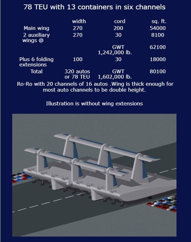
Projected usage, profit and number to be constructedFlying is much more energy efficient than sailing through water. The cost of moving containers is less by using these aircraft. That does not include the financial savings that accrue from the much faster and more direct delivery. Central Asia, Africa, South America have large populations with very poor connections for heavy cargo. Just supplying the cargo needs of these and similar areas will require a large number of these very heavy lift container aircraft. The auto, truck, passenger ferry versions will transform Indonesia, the Philippines and many other areas. Passenger train speed will be provided at bus fare cost where roads are poor. This will greatly reduce transportation cost while providing good profits. Because of the great profit potential to the owner, the aircraft should sell at a good profit. The small versions obviously are within commercial reach. It will remain to be seen how large ConcordLift™ will become. Roll On – Roll Off new car delivery is an obvious use for the largest version, since it is high volume and low weight.
In the coming years major improvements in materials will make it more useful. The weight of structure will be lighter, stronger, making possible larger versions. It may be possible to fly without using any fuel, if the great wing surfaces were covered by improved photovoltaics. Dedicated ConcordLift ports will be constructed. Could this become 600 feet wide, 300 feet in cord, with 6 auxiliary wings over 12 million pound load? Bulk products would not need transportation to ocean ports. Inaccessible places would come within easy reach. A version the size of a light plane could deliver 10,000 pounds to a short unimproved field. The airline industry focus is on faster, higher, sexy! That can only be done at higher cost to build and operate – higher ticket prices! Which would transform travel more, USA to Europe in one hour at much higher cost, or Mumbai to Bangalore in 10 hours for bus fare?
VII Origin of idea and reason for name
Except for work on distributed load, span load, there are no parallels in published work. The ConcordLifttm configuration and operation has nothing in common with papers on lifting body, wing-in-ground, three wing, or flying wing. There are no papers, or prior art, to reference that would increase understanding. This needs new original research and development. Lifting body and triplane aircraft proposed and constructed are totally different concepts. The essential features are: very deep cord wing, with auxiliary wings for control and the lift needed for take off and landing,. Some designs may not require the two stage landing gear. The main and auxiliary wings could be cantilevers to support a central load or fuselage.
The name for this aircraft configuration,
ConcordLifttm”, because the wings work in concord - harmony - to lift the great weight, is specified in USPTO Patent Application Publication US 2011/0168832 A1. The International Patent Publication numbers are WO/2011/0816635, PCT/US2010/002124.